XRCC Tutorial - Crime Scene
Overview
In this tutorial, we'll guide you through how to build a mini crime mystery VR experience, where the player will hold a camera, find and take pictures of evidence in order to reconstruct the events that happened at the scene.
This tutorial project contains visual effects, including flashing lights and rapid changes in brightness, which may trigger photosensitive epilepsy in some individuals.
If you are sensitive to flashing lights or have a history of seizures, please proceed with caution.
Techniques Covered
| Specific Techniques Covered | |
|---|---|
| |
| |
|
Tutorial Project
You can download the project files for this tutorial in two formats: a starter project for step-by-step guidance and a completed project for your reference.
Gameplay Flow
- You are role-playing as a detective in a crime scene
- You need to investigate the scene
- Find all evidence using a camera
You are encouraged to make adjustments to the project as you see fit — part of the fun in game-making is bringing your unique concepts to life!
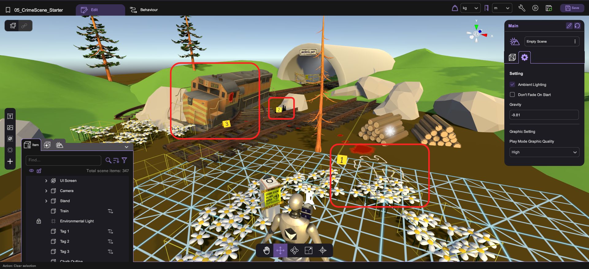
Assets Provided in the Starter Project
The starter project for the Crime Scene tutorial provides a comprehensive set of assets and functionalities to get you started. This includes some 3D models for building the scene. Additionally, the project includes some items for investigating the scene such as a train, bottle and camera. With these assets and functionalities in place, you'll be able to build a complete example of the game flow.
Set Up the Camera
Add the Flash Visual Effect
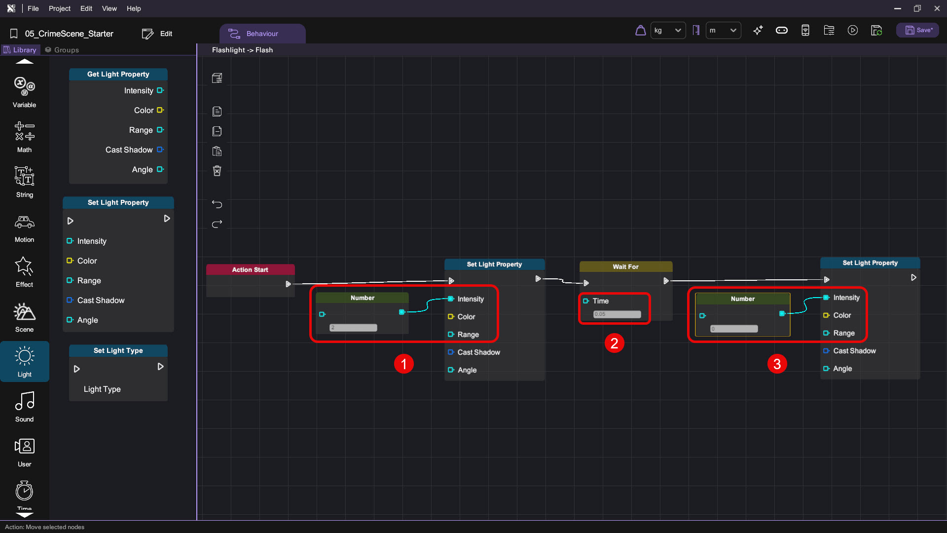
We know that a real-life camera flashes briefly when taking a photo. In XRCC, we can achieve this by turning the camera on, adding a small delay, and then turning it off.
- Select Camera > Flashlight then switch to the Behaviour tab.

- Go to Groups then click the "+" icon to add a new behaviour group.

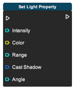
- For the new behaviour group, set Toggle Action to true and rename it as Flash. We have just added a Flash action to the camera flashlight. Then, implement the flash logic with the following nodes:
| Category | Behaviour |
|---|---|
 |  |
 |  |
Equip the Camera
To allow the player to hold the camera and take pictures, we need to utilize the Equip node in XRCC.
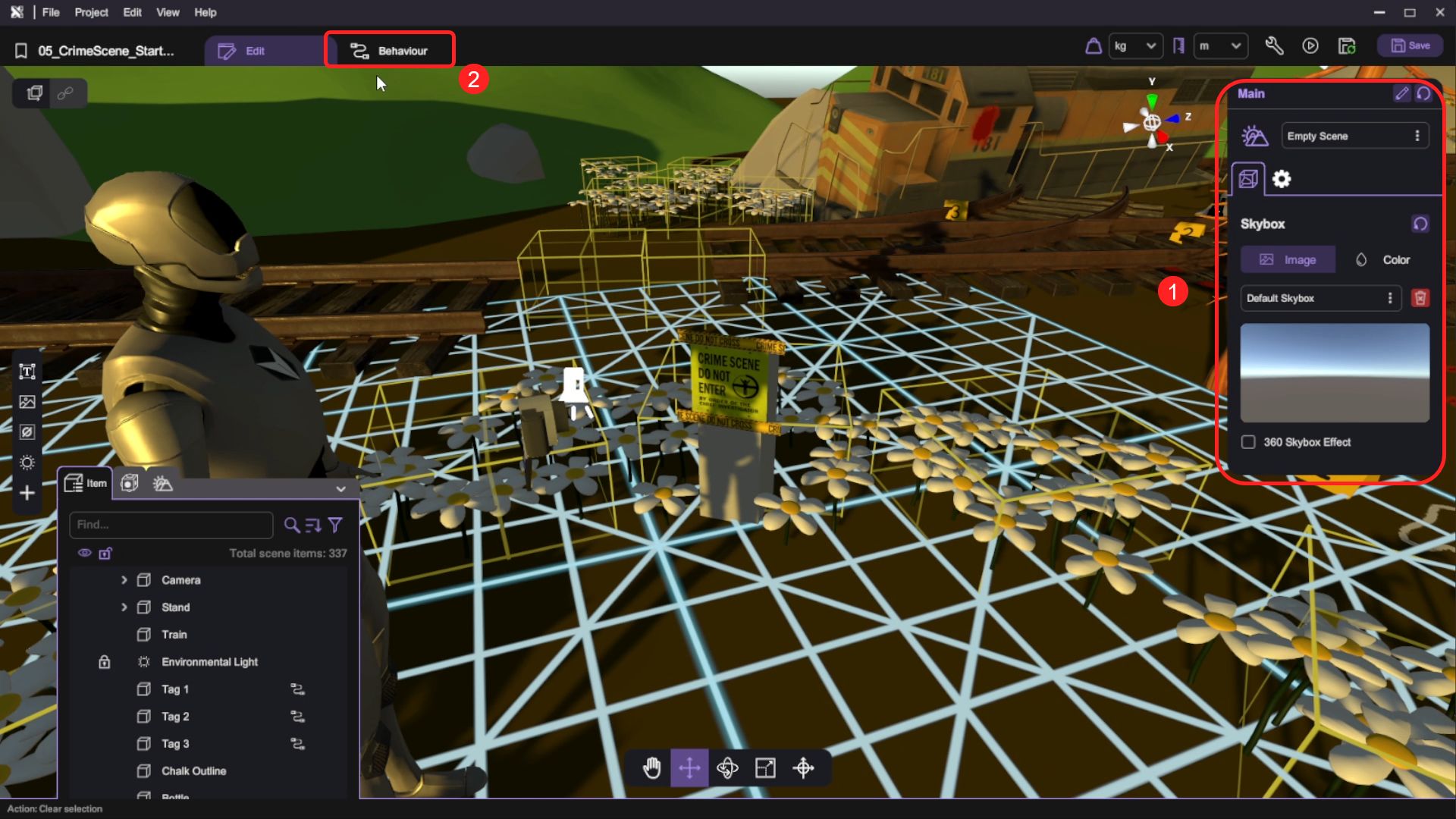
- Click on the sky so that your inspector now focuses on the Main scene.
- Switch to the Behaviour tab
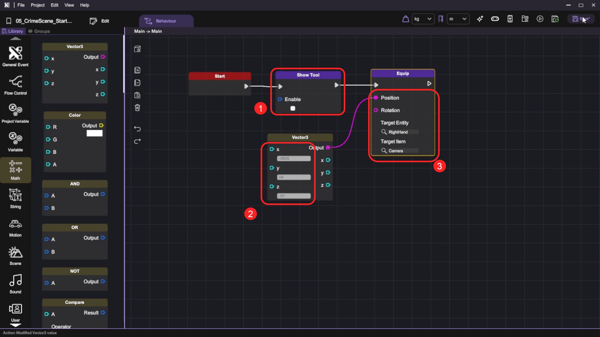
- Implement the equip camera logic with the following nodes:
- Start -> Show Tool (enable=false) -> Equip (position=vector3(-.0635, .04, -.01), targetEntity=RightHand, targetItem=Camera)
- Implement the equip camera logic with the following nodes:
| Category | Behaviour |
|---|---|
 |   |
 |  |
Run your project. Check that:
- The camera mesh is equipped to your hand in XRCC.
It is a good practice to run your project once in a while to check if you have done anything wrong, so that you can fix it now rather than later.
Set Up the Clipboard and UI
After setting up the camera, it'd be nice if our game has a way to tell the player how many remaining photos still need to be taken in the crime scene.
Add the Clipboard Mesh
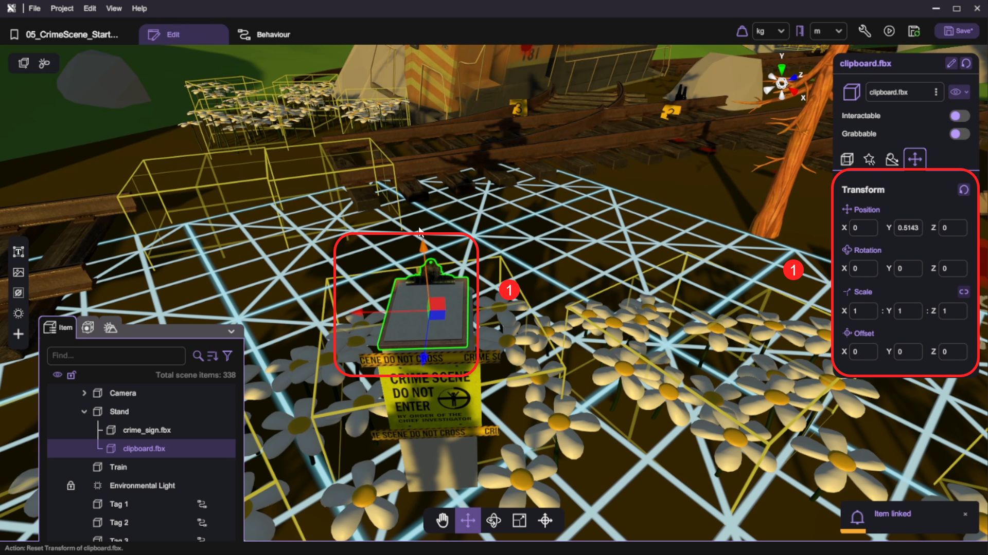
- Open the Asset Panel and select the clipboard mesh at 3D Model > clipboard.fbx, then click Add Asset.

- Select the clipboard mesh, click the link icon, then hover your cursor to Stand and left-click to parent the clipboard mesh under Stand.
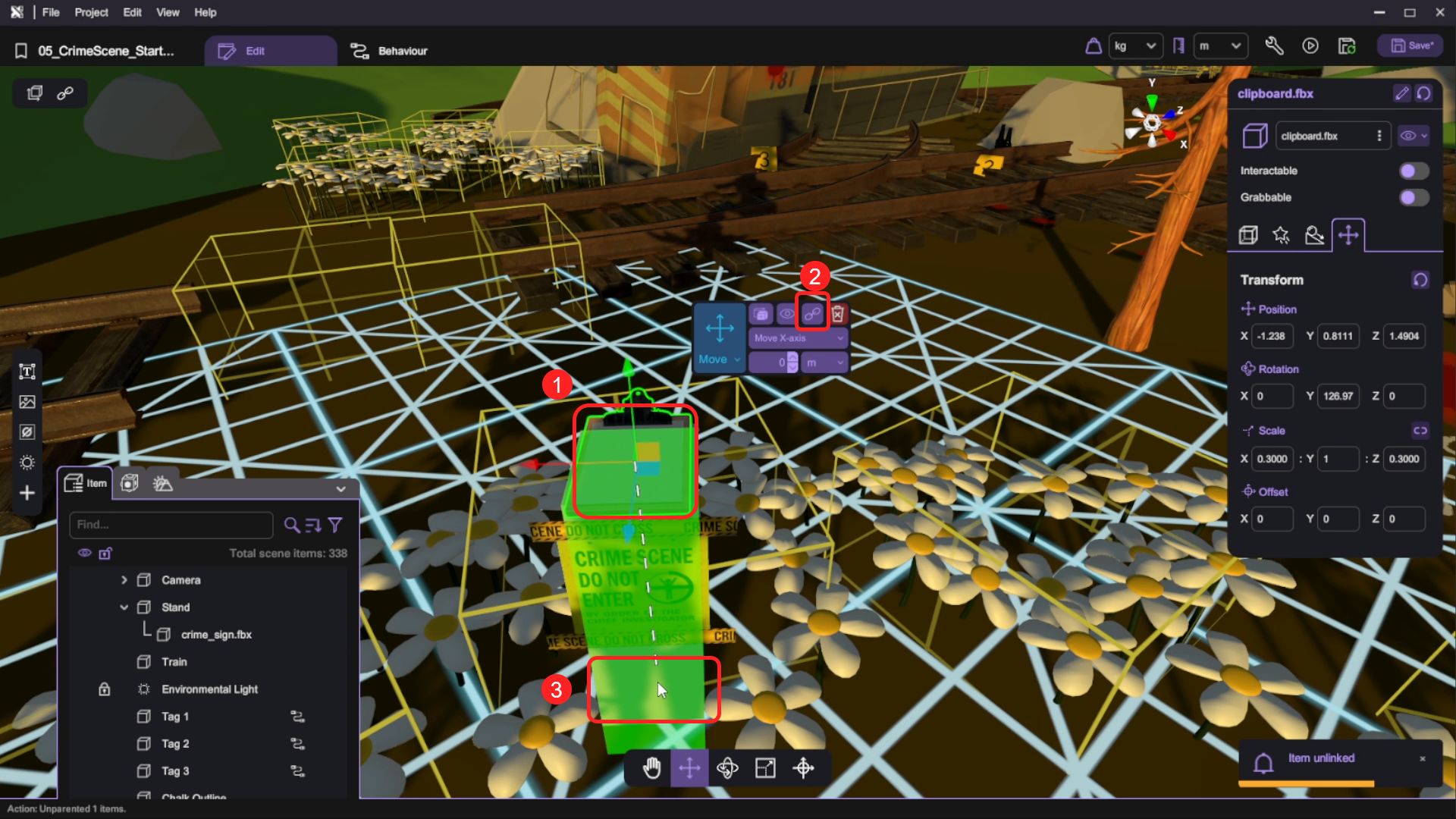
- Adjust the clipboard mesh to the top of the Stand, as long as it's at a place where the player can see the clipboard clearly, it'll be fine. In the picture below, we have set the clipboard's position to (0, 0.5143, 0), rotation to (0, 0, 0), scale to (1, 1, 1).
The clipboard's position may not be exactly the same, you can enter your preferred value.
Display Number of Remaining Photos
- Click on the sky so that your inspector now focuses on the Main scene. Then:
- Switch to Behaviour tab.
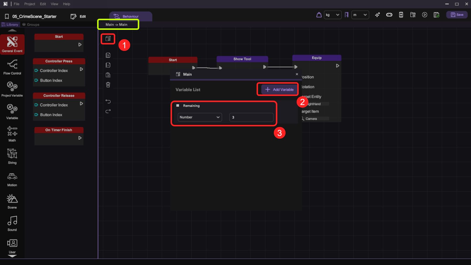
- Open up the Variable panel at the top-left corner of the canvas. Click on Add Variable to add a number variable then rename it as Remaining. For this project, we will have 3 pieces of evidence so set its default value to 3.
- Add two text objects into the scene and parent them both to the clipboard mesh clipboard.fbx. Rename one as Remaining and another as Label.

-
Set the Label text object's text to "Photo(s) Left", font size to 5. Set the Remaining text object's text to "0", font size to 40.
-
Adjust the two text objects to align with the clipboard. Any alignment of the two text objects would be fine as long as they look like writings on the clipboard.
The text position may not be exactly the same, you can enter your preferred value.

- Select the Remaining text label in the scene and open up its Behaviour tab. Implement the number display logic with the following nodes:
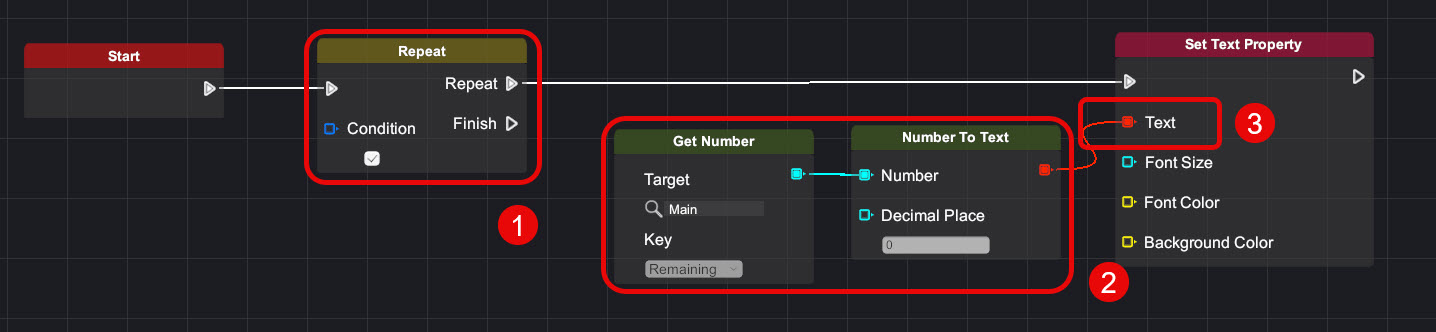
| Category | Behaviour |
|---|---|
|  |
 |   |
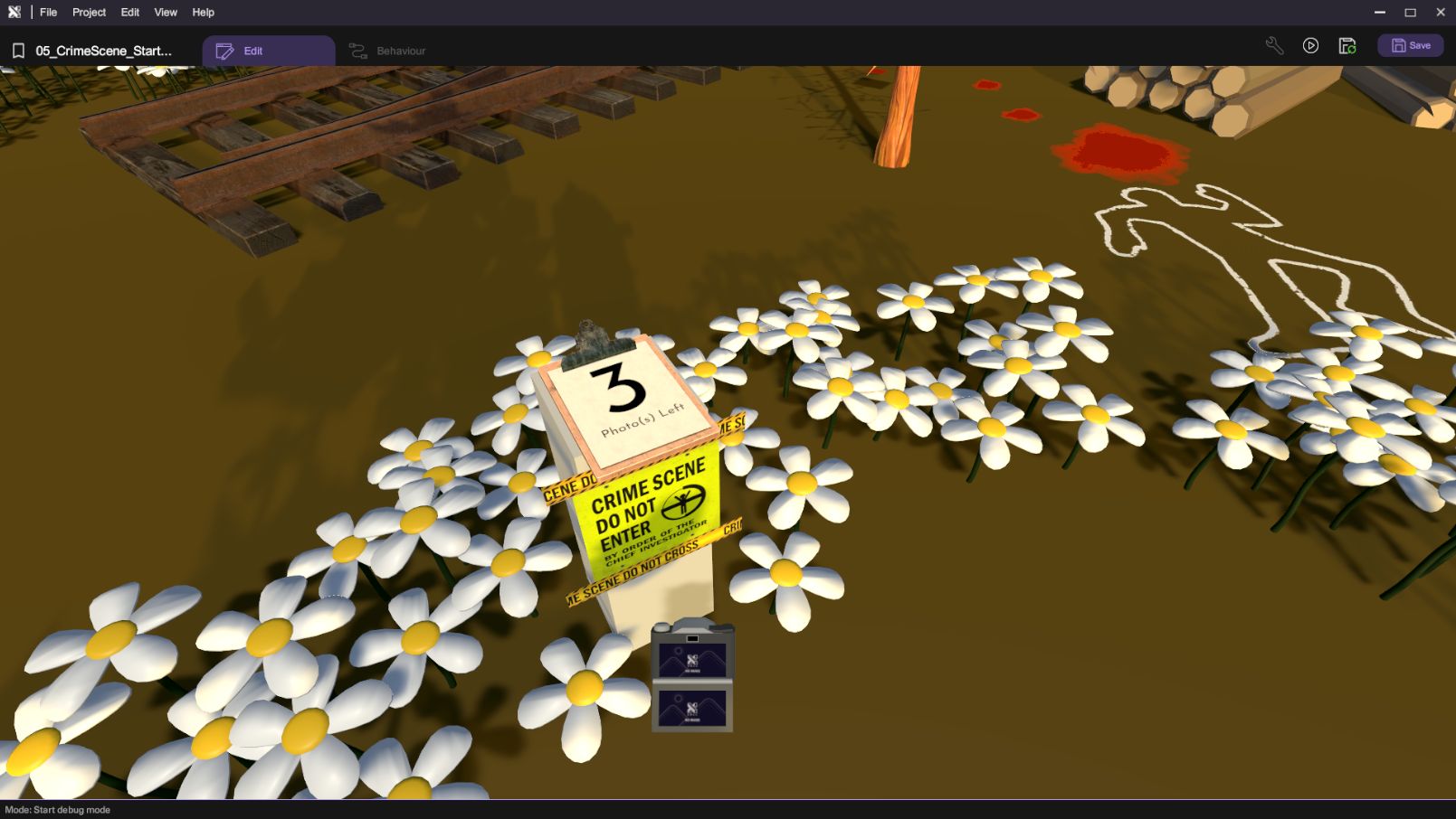
Run your project. Check that:
- The clipboard displays the number of remaining photos.
Display Number of Remaining Photos (UI Screen Alternative Approach)
This section is an alternative approach that utilizes the UI Screen instead of the clipboard to display the number of remaining photos.
This is an optional route.
- (Optional) Add a 2D text object in the scene and set its size as 25. Rename it as Remaining Text.
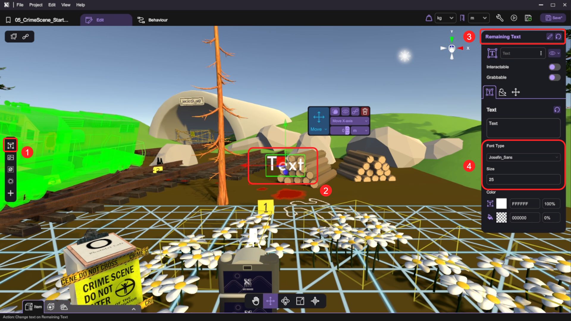
- (Optional) Open its Behaviour tab. Implement the following nodes:
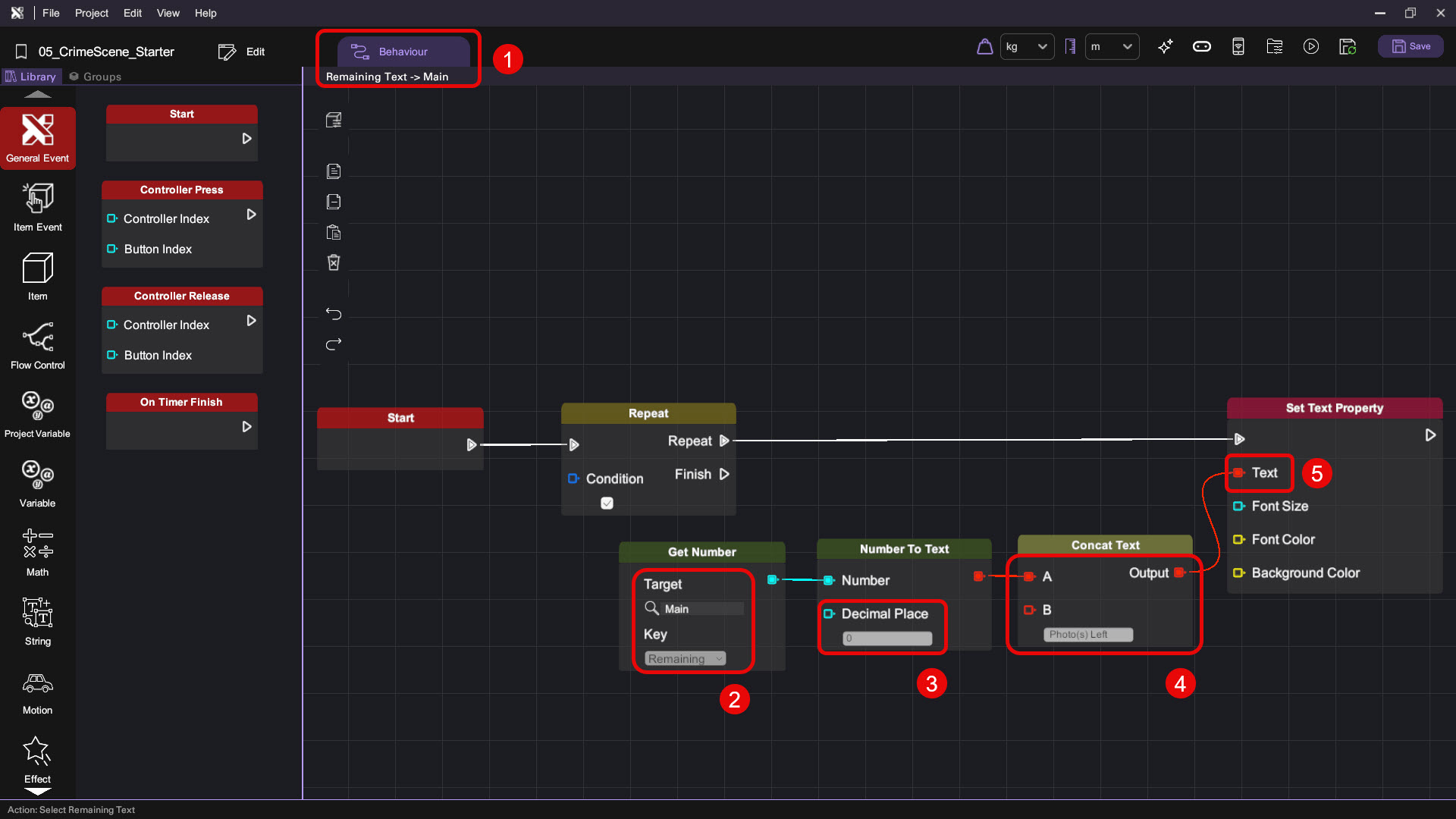
| Category | Behaviour |
|---|---|
| |
| |
 |  |
- (Optional) Go back to the scene and switch to the Entity tab. Then tick UI Screen to enable the UI entity.
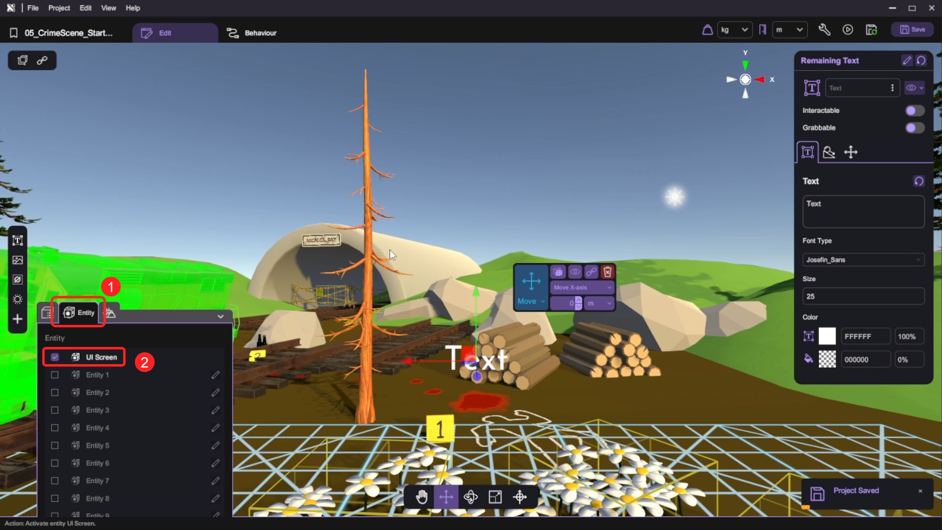
- (Optional) Switch back to the Item tab. Parent Remaining Text under UI Screen.

- (Optional) For Remaining Text, adjust its position, rotation and scale so that when we run the game, the player can see the UI text on the screen.

If you have chosen to use the UI screen approach, check that:
- You can see the UI text in the top right corner of your game.

Set Up the Evidence
We have provided 3 evidence items in the crime scene. Let’s implement these so players can interact with them.
Add the Pointer Mesh
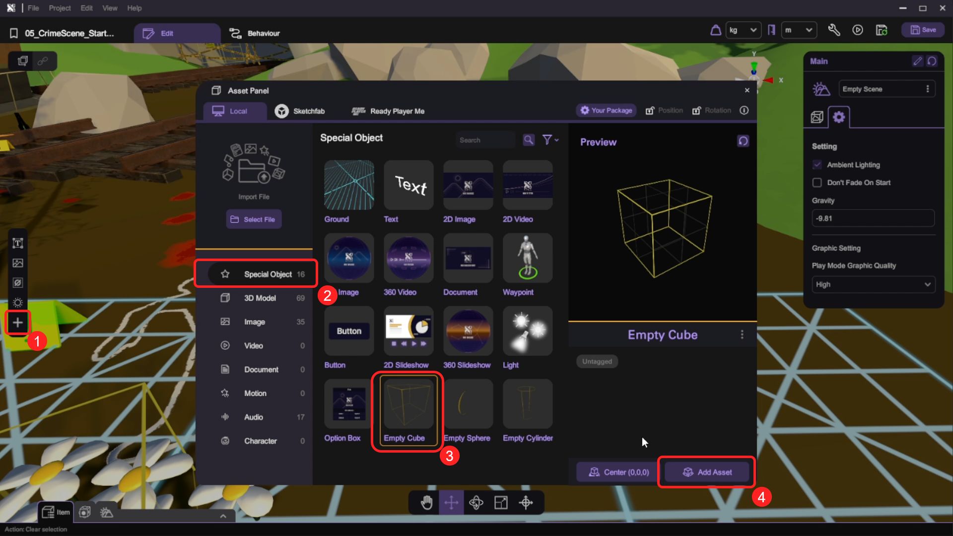
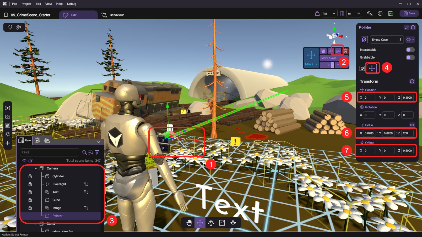
- Open Asset Panel > Special Objects. Then add an Empty Cube into the scene and rename it as Pointer. This object will act as a ray for the camera.
- Parent Pointer under the Camera mesh. Set Pointer's position to (0, 0, 0.1), rotation to (0, 0, 0), scale to (0.02, 0.02, 200), offset to (0, 0, 0.5).
Implement the Collision Check
One of the evidence items will be the huge train in the scene. By utilizing the contact triggers in XRCC, we can know when the player is pointing their camera toward the train.
- Select the Train in the scene.

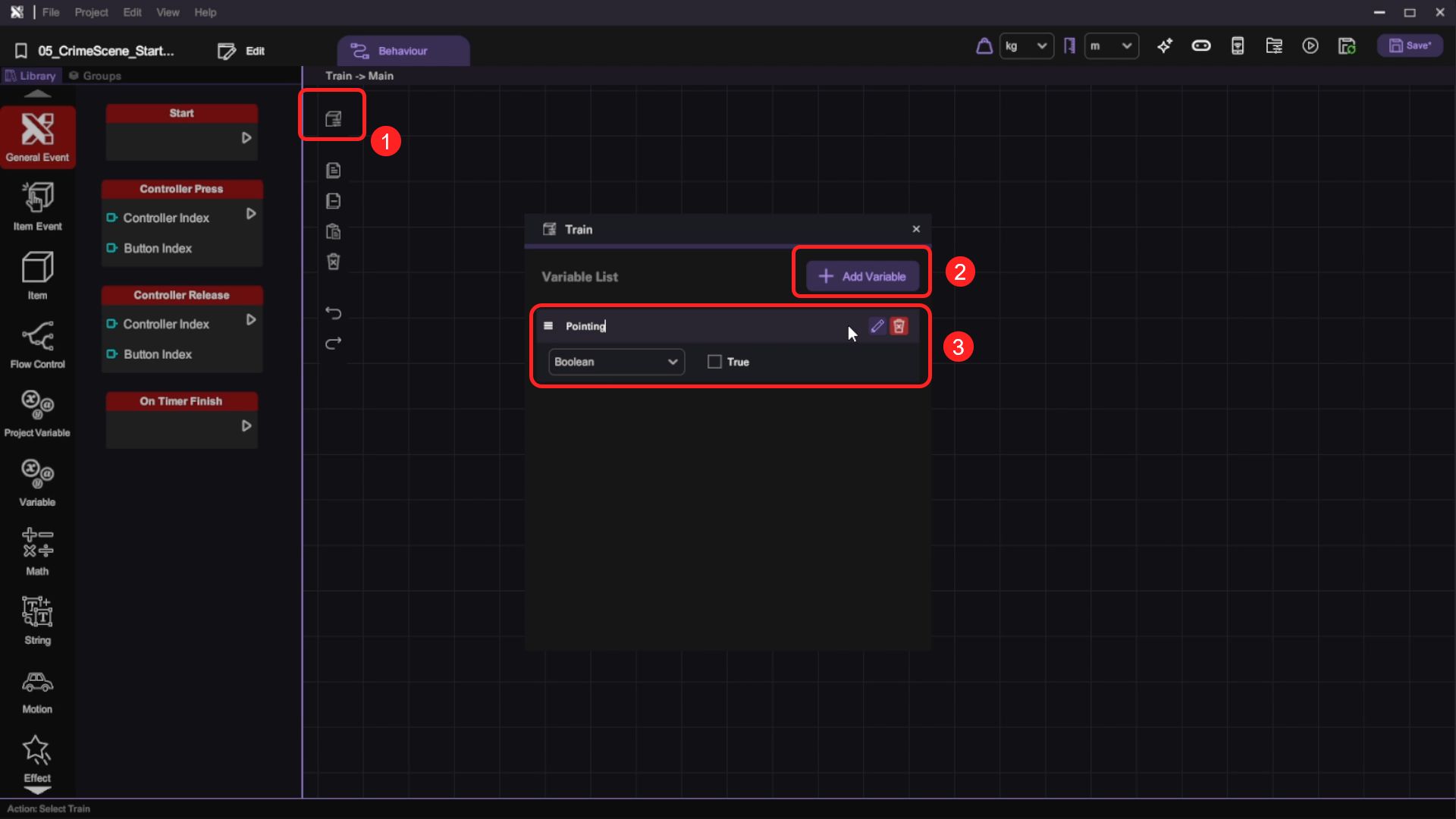
- Open the train's Behaviour tab. Create a Pointing boolean variable and set its default value to false.
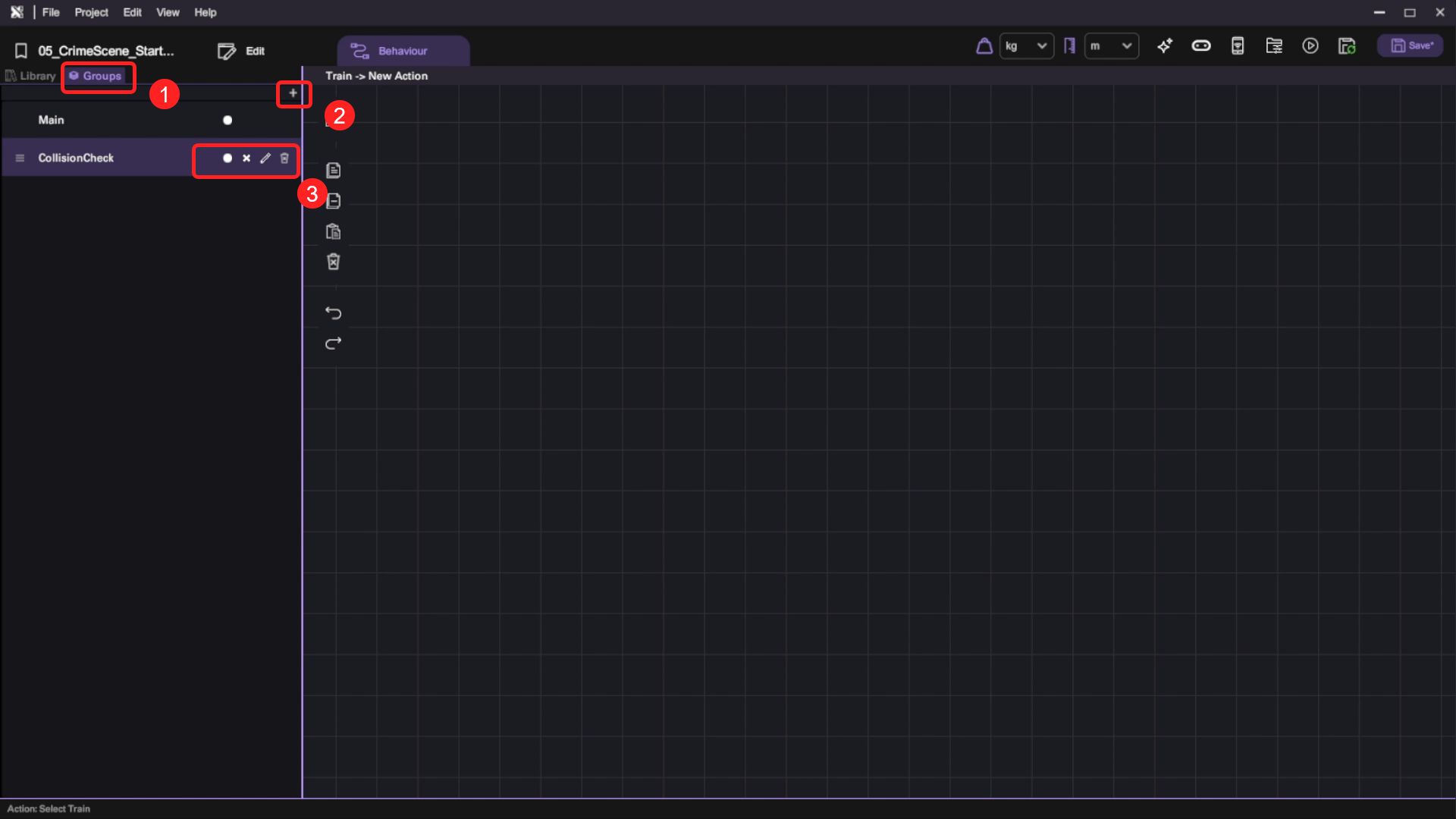
- Add a new Behaviour Group (Toggle action to false) and rename it to CollisionCheck.
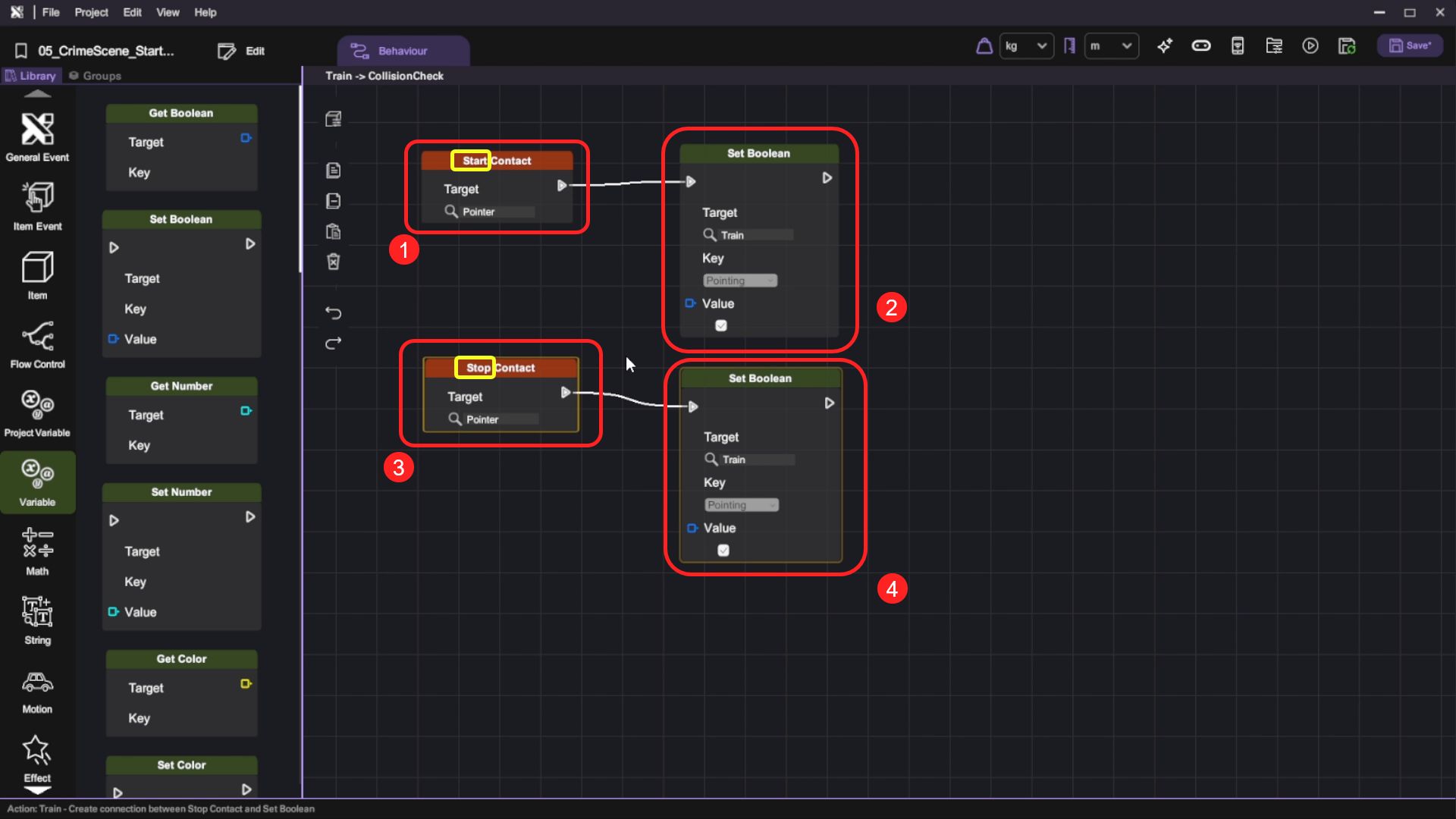
- Implement the collision check logic with the following nodes:
Remember to set the target of both Start Contact and Stop Contact as Pointer.
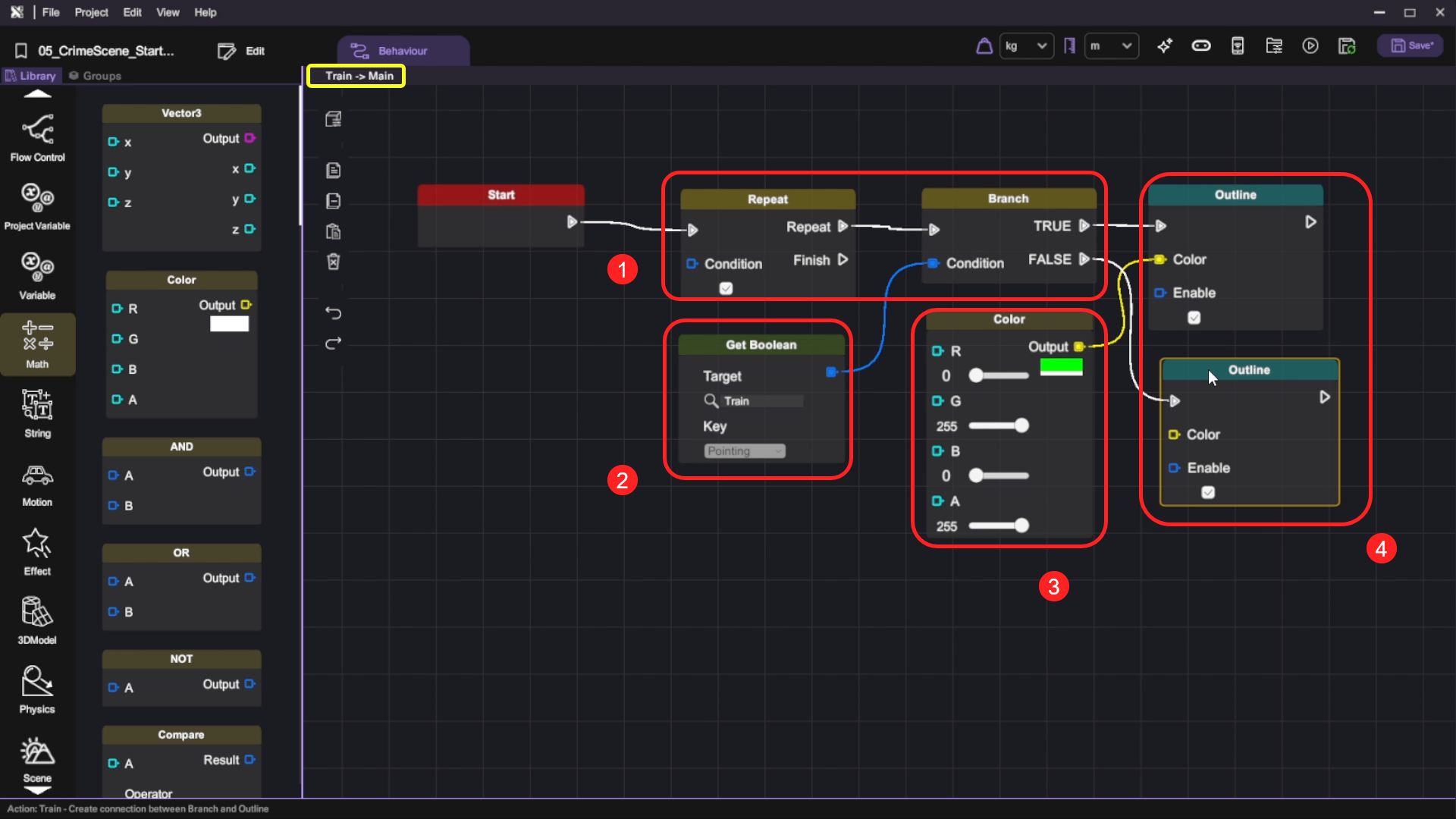
- Let's add an outline to the object when Pointing is true. Switch to Main Behaviour Group of the same object. Implement the logic as shown in the picture below:
| Category | Behaviour |
|---|---|
 |   |
|  |
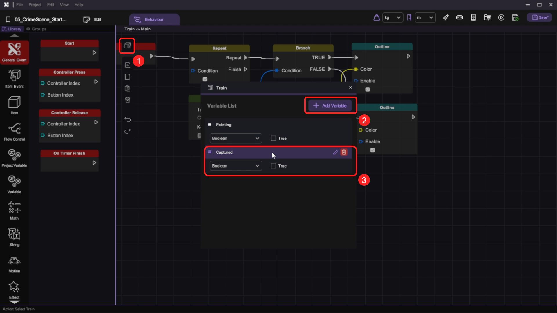
Implement the Capture Behaviour
- Select the Train and open the Behaviour tab. Create a new Captured boolean variable and set its default value to false.
- Add a new Behaviour Group and rename it as Capture.
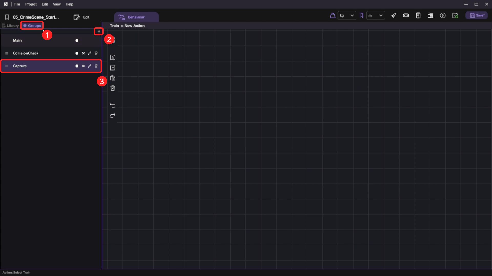
- When the player points their camera to an evidence item that has not been captured yet, we will allow them to take a picture of it. Switch to Capture Behaviour Group and implement this logic:
| Category | Behaviour |
|---|---|
|  |
|  |
|  |
 |  |
- When the player has not captured evidence yet, we want to highlight it to give them a hint. Switch to Main Behaviour Group and implement this logic:

Run your project. Check that:
- The evidence is outlined when the camera points to it.
Combine Everything
At this stage, the only thing left to do is to combine all the key components to finish our game.
Add Sound Effect
Adding the right sound effect can make the camera in our VR game feel a lot more lively.
- Select Train in the scene and open its Behaviour tab. Switch to CollisionCheck Behaviour Group and implement the logic shown in the picture below.
Set both the loop and spatial fields of Play Sound node to False.

- For the Play Sound node, click on the magnifying glass icon then select the camera_focus.wav.

- Switch to Capture Behaviour Group and add Play Sound to the end of our previous behaviour.
Set both the loop and spatial fields of Play Sound node to False.
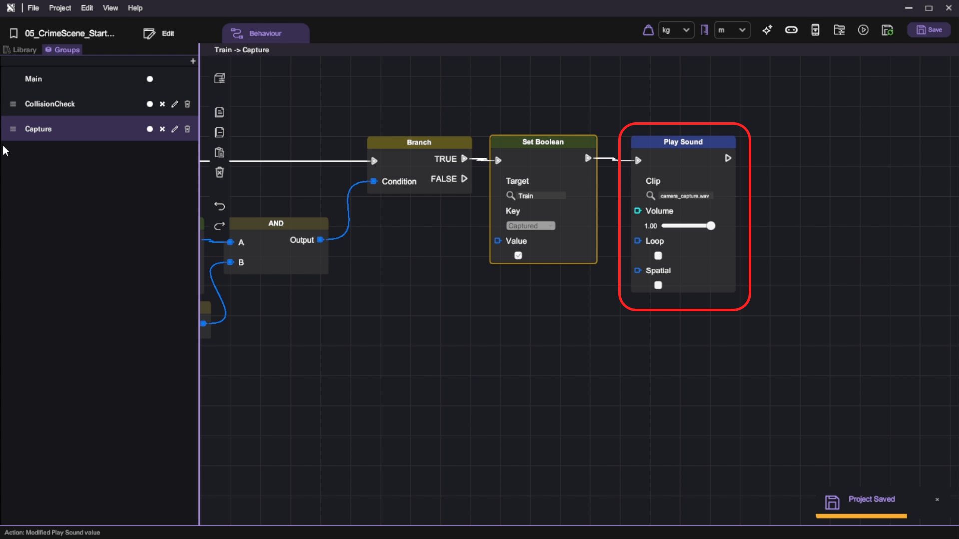
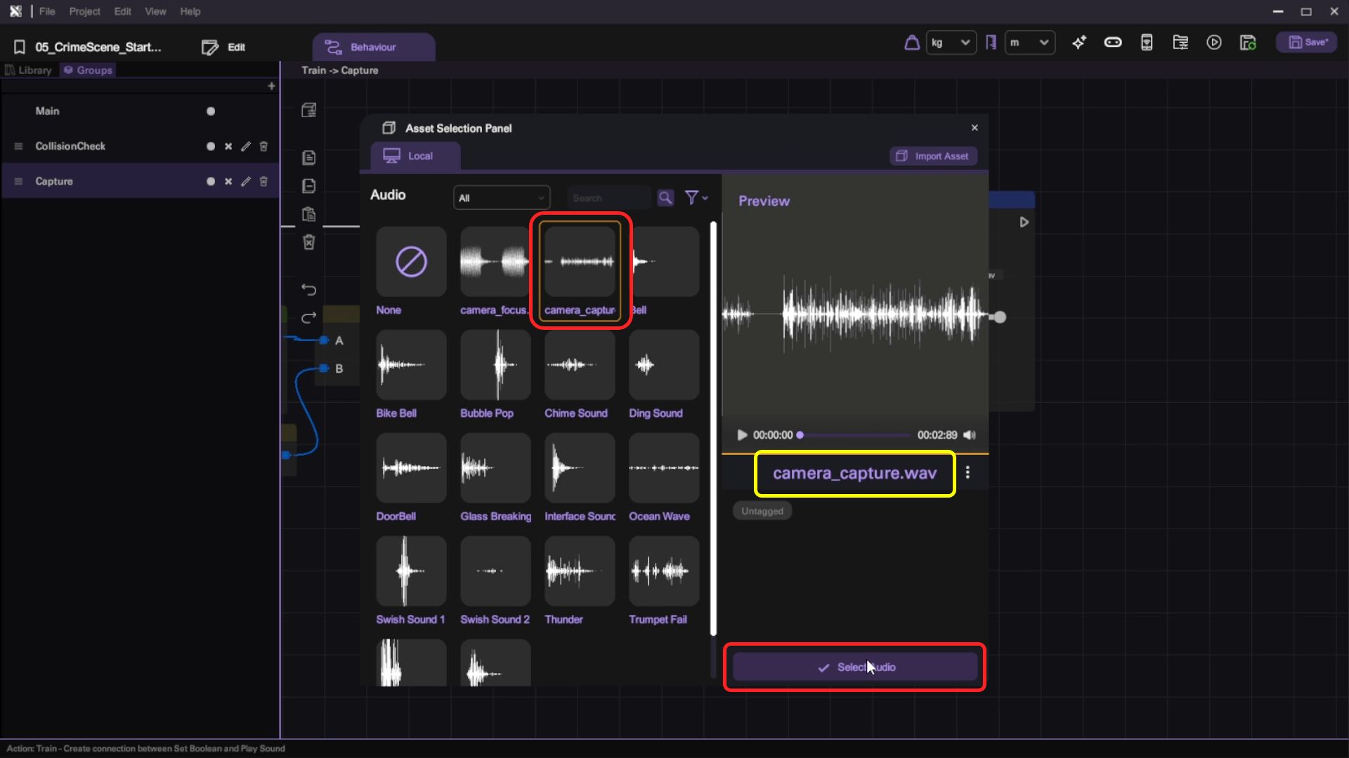
- For this Play Sound node, click on the magnifying glass icon then select the camera_capture.wav.
Call the Camera Flash
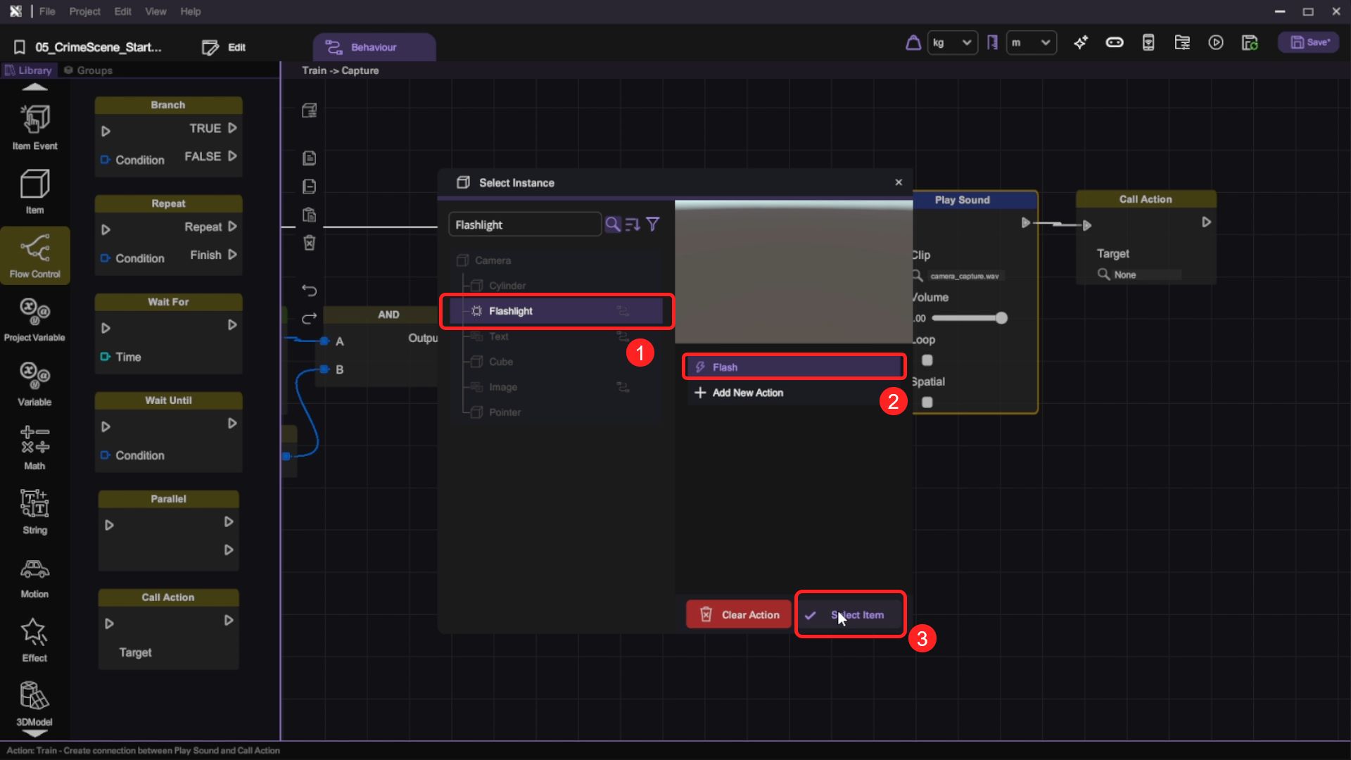
- In the Capture Behaviour Group, add a Call Action node after the Play Sound node.

- For the Call Action node, select Flash action under Flashlight. Then click Select Item.
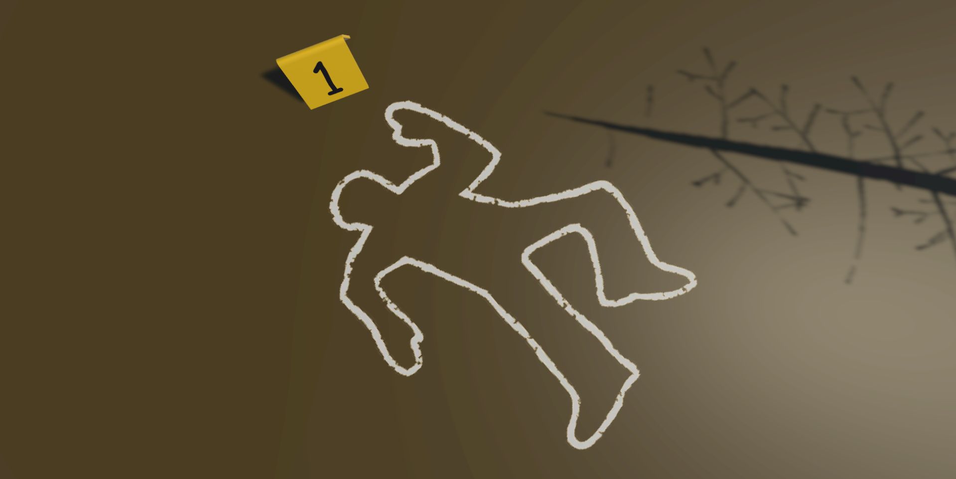
Show the Evidence Tag
To remind the player that they've taken a photo of evidence, we will place a tag in front of it.
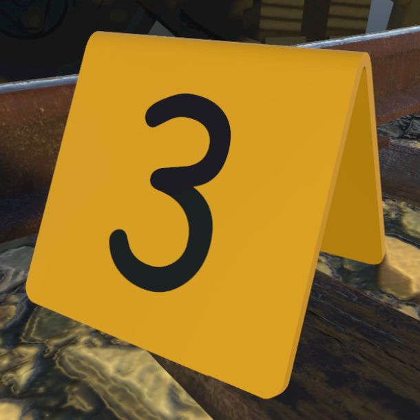
- In the Capture Behaviour Group, add another Call Action node after our previous behaviour. For the Call Action node, select Show action under Tag 3. Then click Select Item.
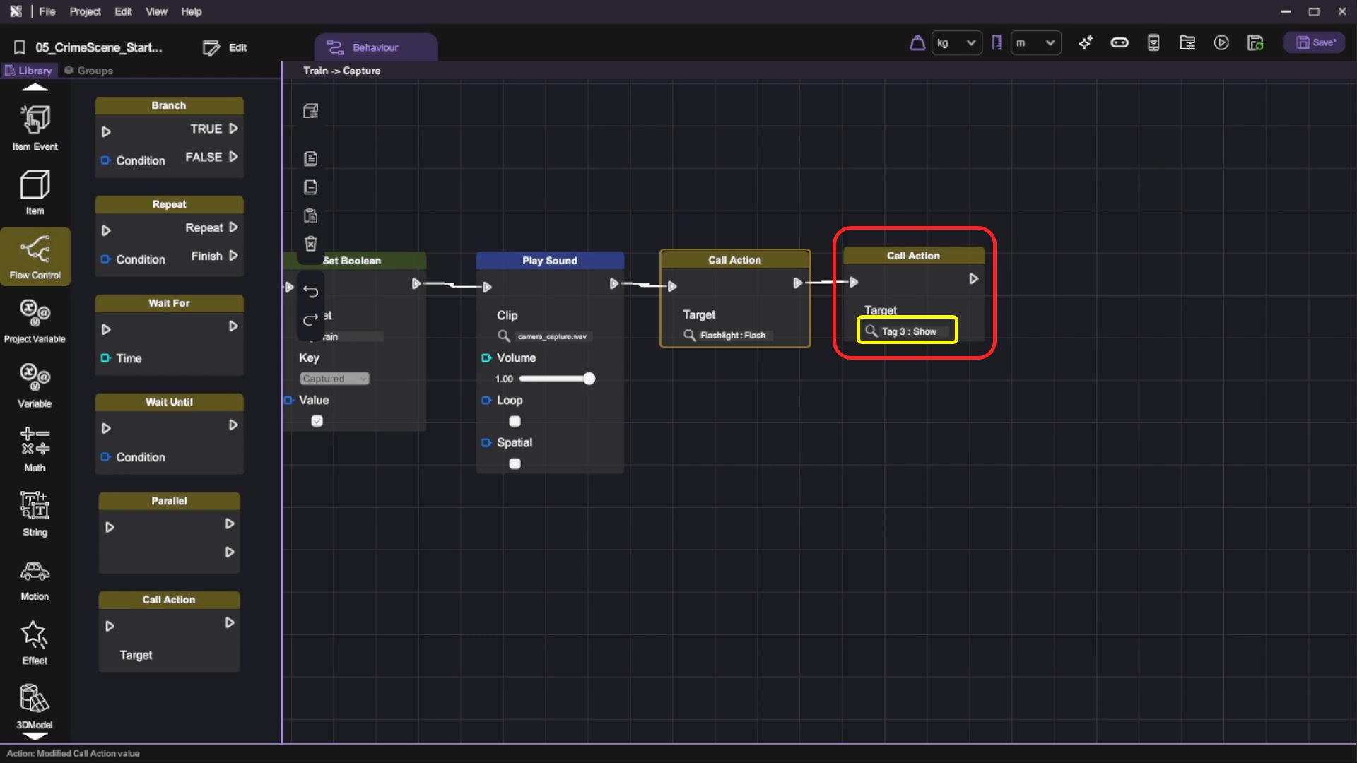
For this tutorial, we have positioned the train to use Tag 3 in advance.
- We also have to subtract the remaining number of evidence by 1 when the player captures a photo. Implement the logic shown below to update the number:

Run your project. If you have followed the instructions correctly, you should be able to:
- Point your camera to the train and (left click to) take a photo
- Hear camera focus and capture sound effects (You'll need to plug in earphones to test this)
- See a tag appear after you've taken the photo
- See the remaining number of evidence has been updated on the clipboard
Show Images on Camera Screen
Up until now, our camera doesn't really show anything on its screen. We can utilize Set Image node to display the result image on the camera screen.
- Select Camera > Image in the scene.

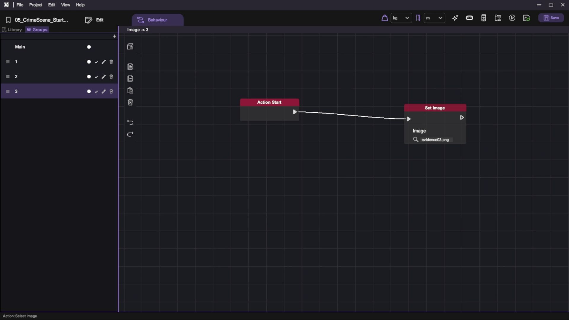
- Open up the Behaviour tab. Since building this part of the game is a bit redundant, you'll see that we have already prepared 3 actions in this object for setting 3 separate evidence images. You'll only have to remember that we'll call these actions from other objects in the game.
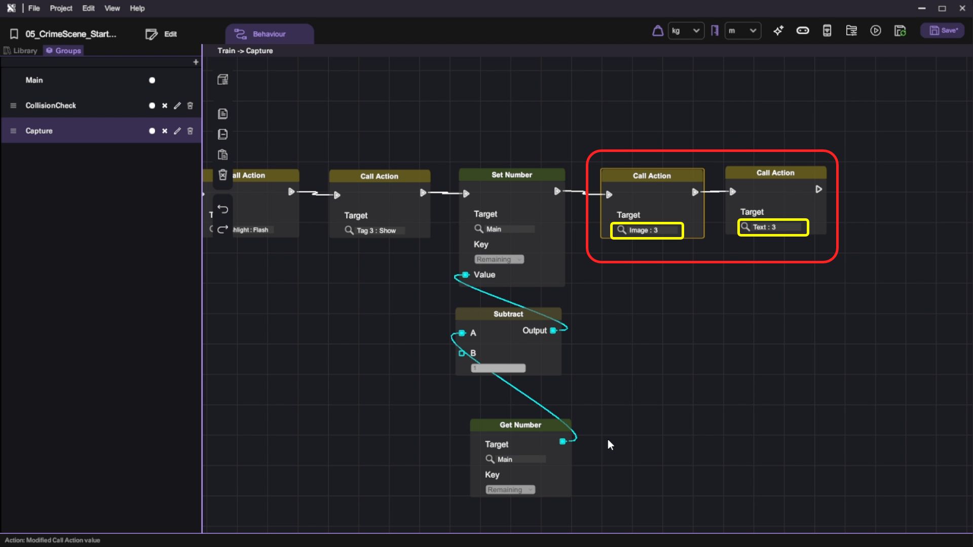
- Select Train in the scene again and open up its Behaviour tab. Go to Capture Behaviour Group then add two Call Action nodes.
- For the first one, set it to the "3" action under Camera > Image.
- For the second one, set it to the "3" action under Camera > Text.
Run your project. Check that when you (left click to) take a photo:
- The camera screen displays the result image
Extend the Behaviour to All Evidence Items
We have finished the behaviour for one piece of evidence. By duplicating objects and making slight changes, we can extend the behaviour to all 3 pieces of evidence: the train, bottles and body outline.
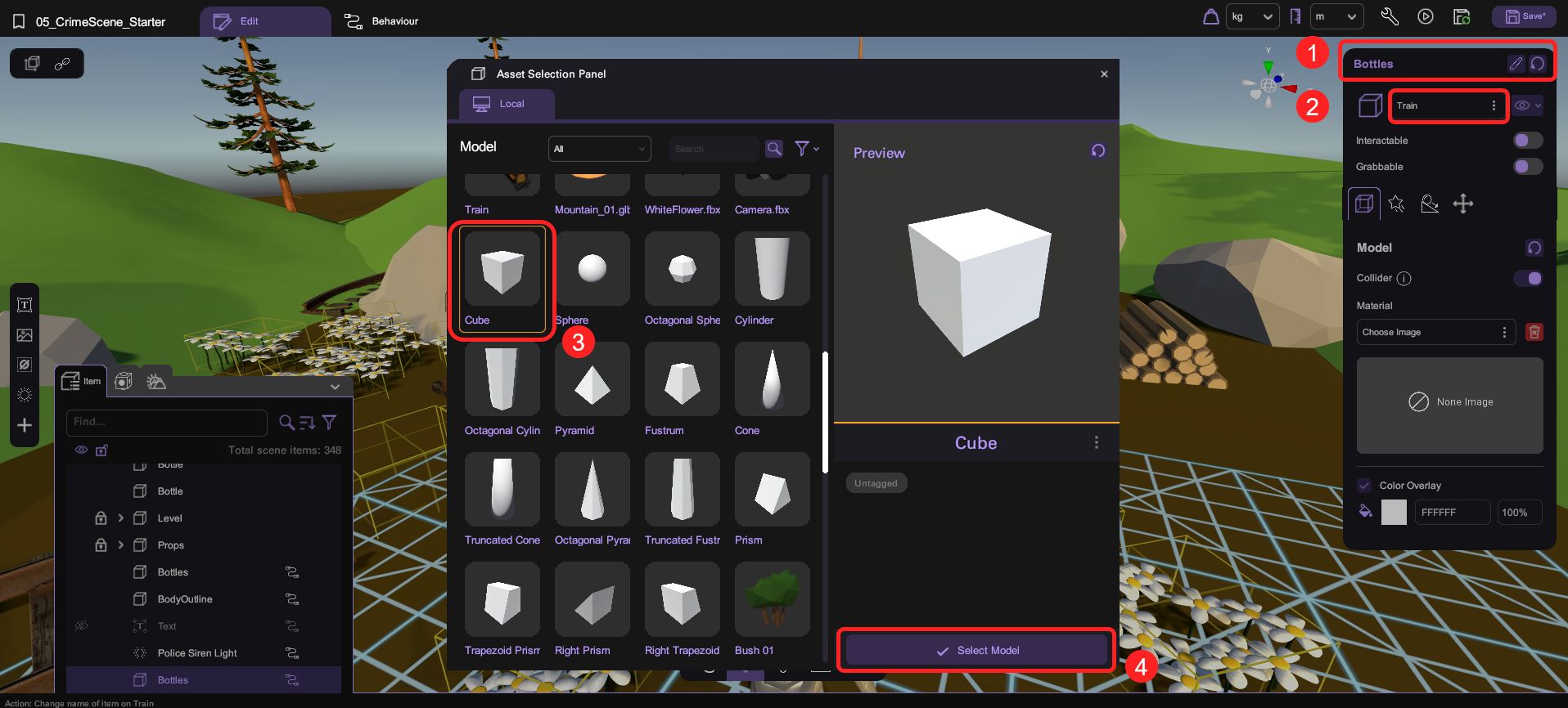
- Select Train in the scene. Duplicate the Train and rename it as Bottles.

- Set the 3D model of Bottles to a cube and set its color overlay to FFFFFF 0% (transparent). Then, adjust the position, rotation and scale of Bottles so that it covers the three bottles in the scene. This will be the "hitbox" of our bottles in the scene.
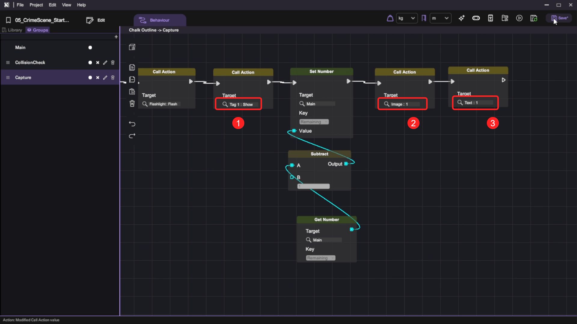
- Open up its Behaviour tab. Go to Capture Behaviour Group and modify the following nodes:
- For the "Tag 3: Show" Call Action node, set the target to Show action under Tag 2.
- For the "Image: 3" Call Action node, set the target to "2" action under Image.
- For the "Text: 3" Call Action node, set the target to "2" action under Text.

- Now do the same (from 1 to 3) for the body outline.

Run your project. Check that:
- You can take pictures of the train, bottles and body outline.
- You can see the tag appear in front of the evidence.
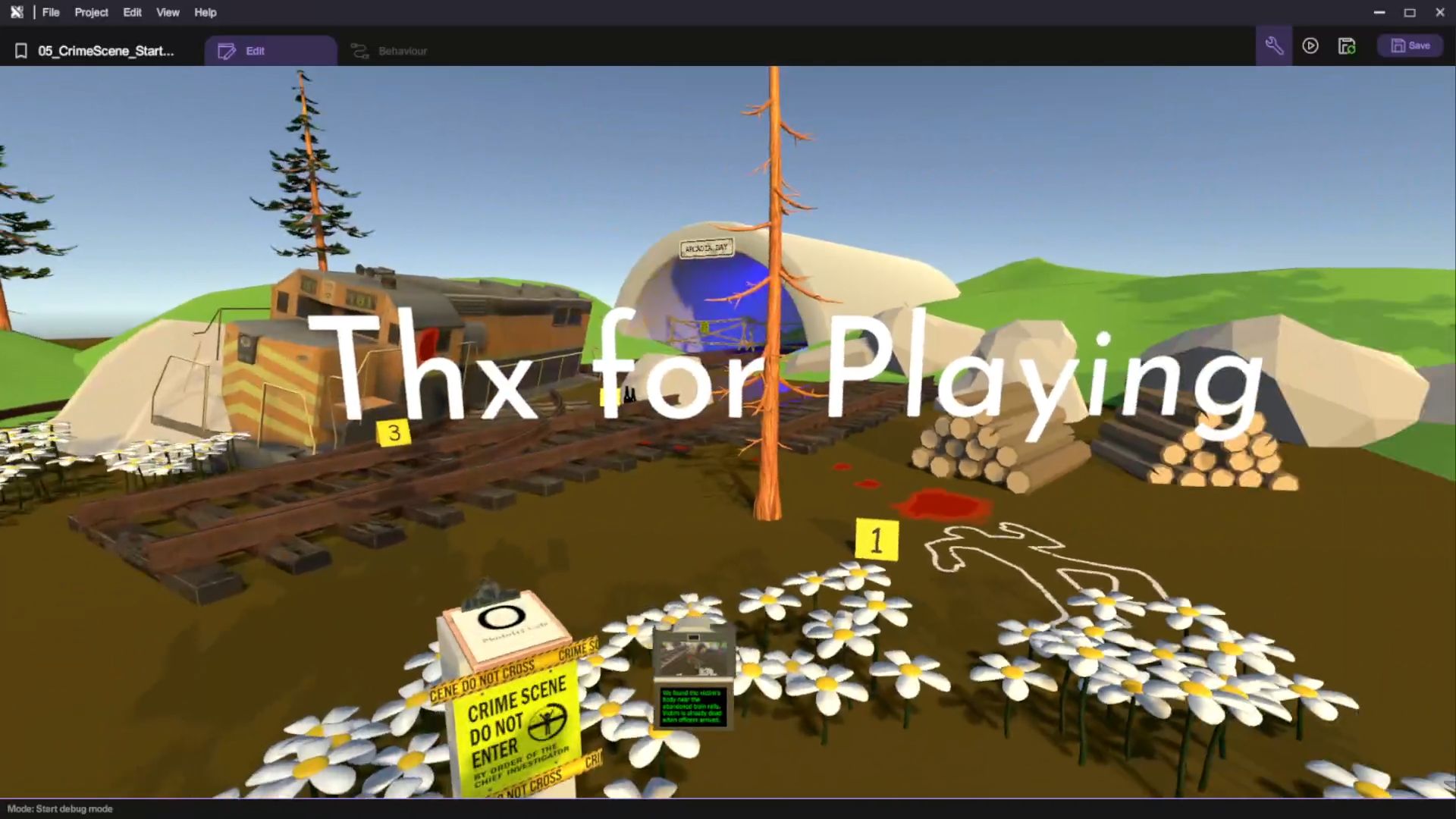
Create a Thanks For Playing Message
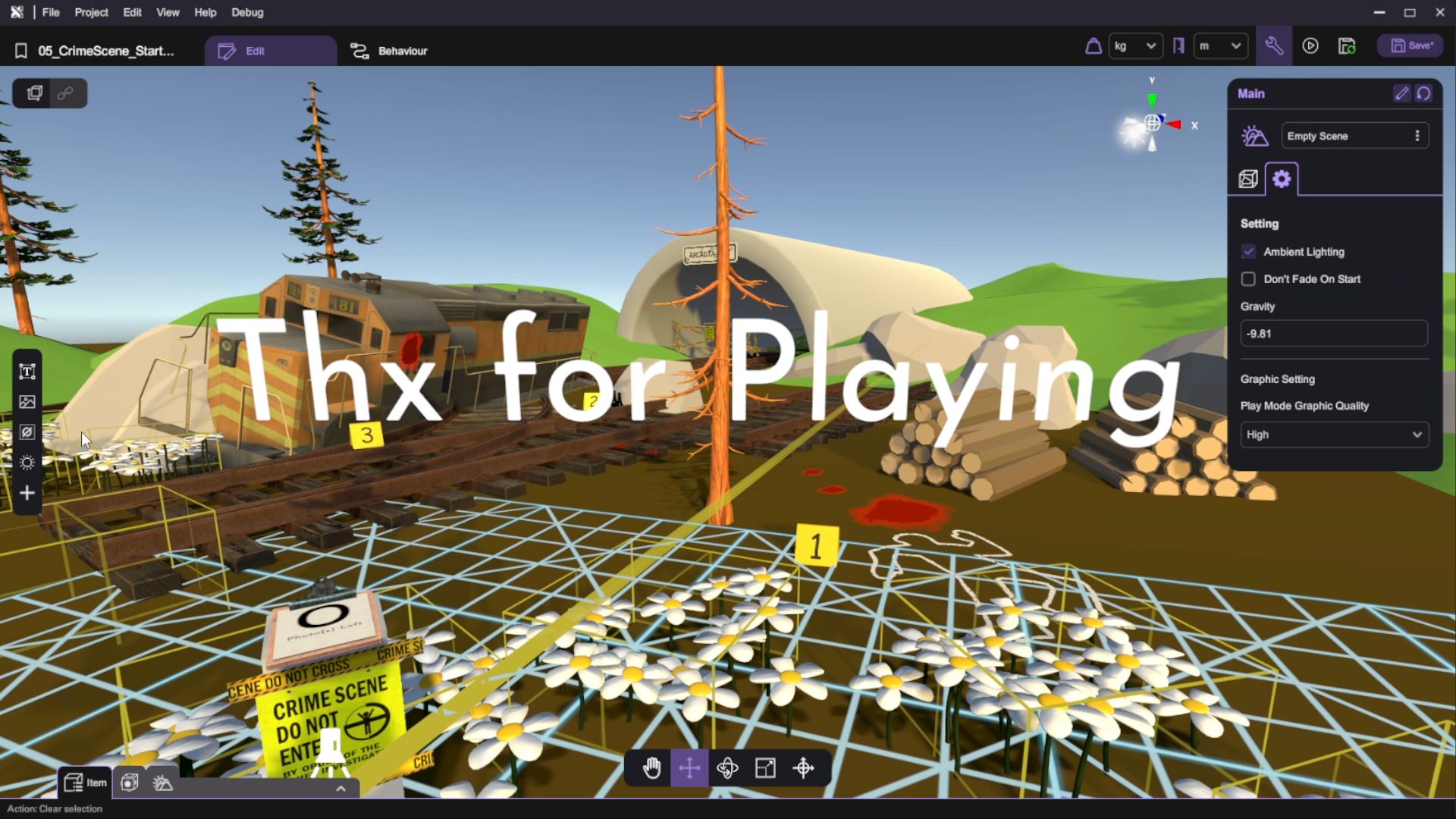
Finally, let's create a Thanks For Playing message for the player when the game has ended.
- Add a 2D text object in the scene and rename it as Victory.
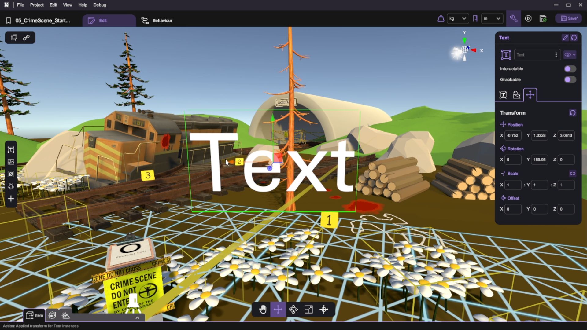
- Let's edit the text object so that it shows Thx for Playing (Or any messages you'd like to show e.g. Credits: Made by XXX).
- Switch to its Behaviour tab. We can implement the display logic with the following nodes:
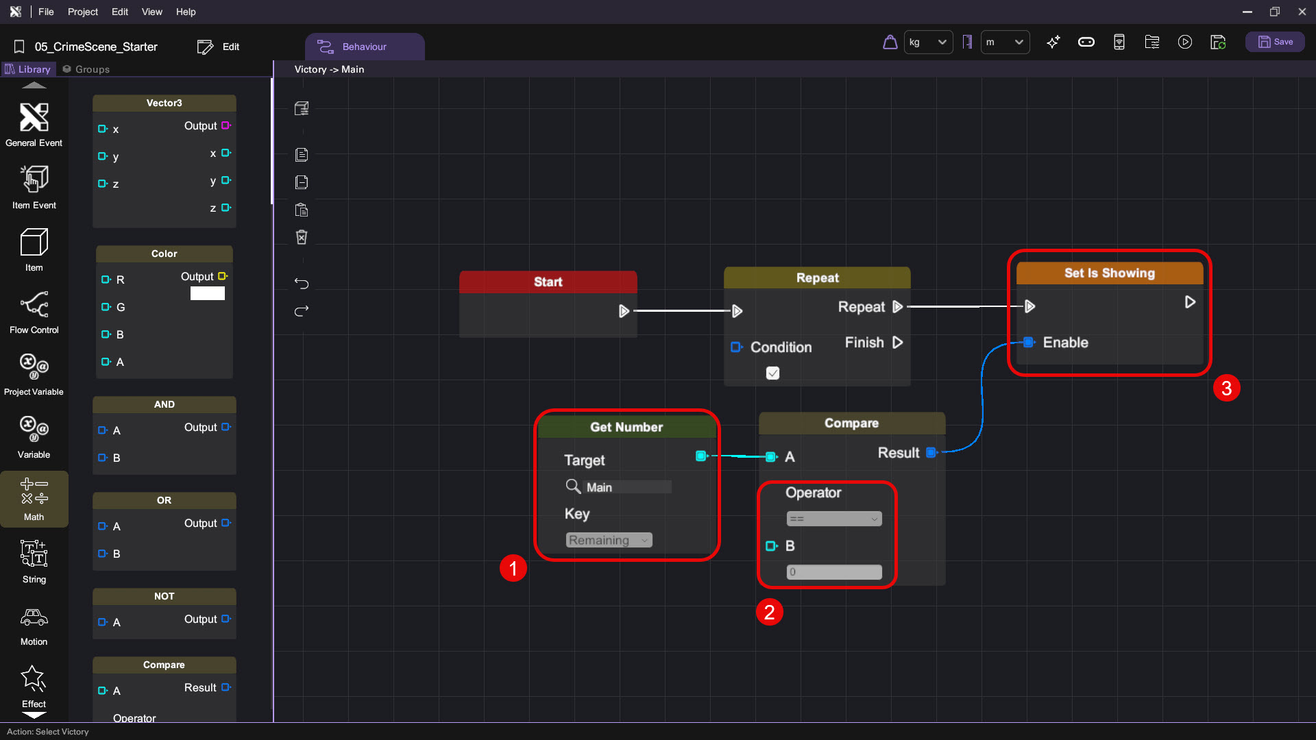
Run your project. Check that:
- The Thanks for Playing message is shown when the remaining number of photos reaches 0
Advanced Challenge: Police Siren
This section requires understanding in trigonometry maths.
In this section, we are going to utilize the sine function to build police siren lights. This subtle environmental light can add another layer of immersion to our game.
- Add a light object to the scene and rename it as Police Siren Light. Then, position it near the end of the track inside the tunnel. Set light type to Point, set intensity to 2 and set range to 20.

- Open up the Behaviour tab. Add two number variables - MaxRange and Frequency, then set their default values to 20 and 1.5 respectively.

Police siren lights typically flash at a frequency of 1 - 4 Hz
- By utilizing the sine function, we can implement the periodic flash behaviour of a police siren light in this way:
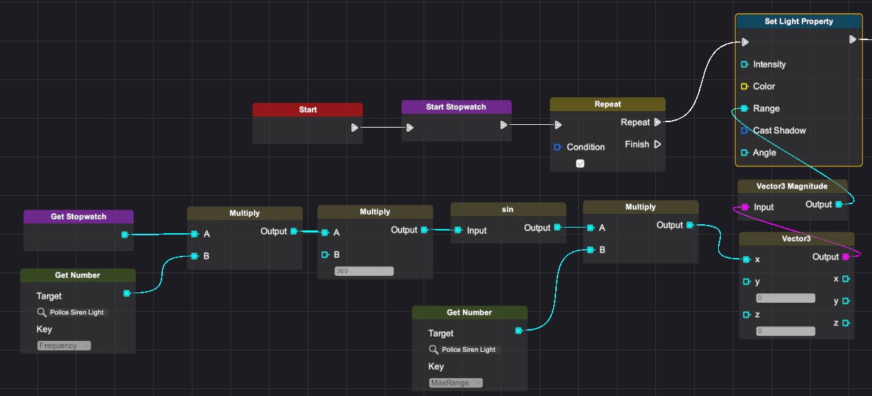
| Category | Behaviour |
|---|---|
| |
| |
|    |
 |   |
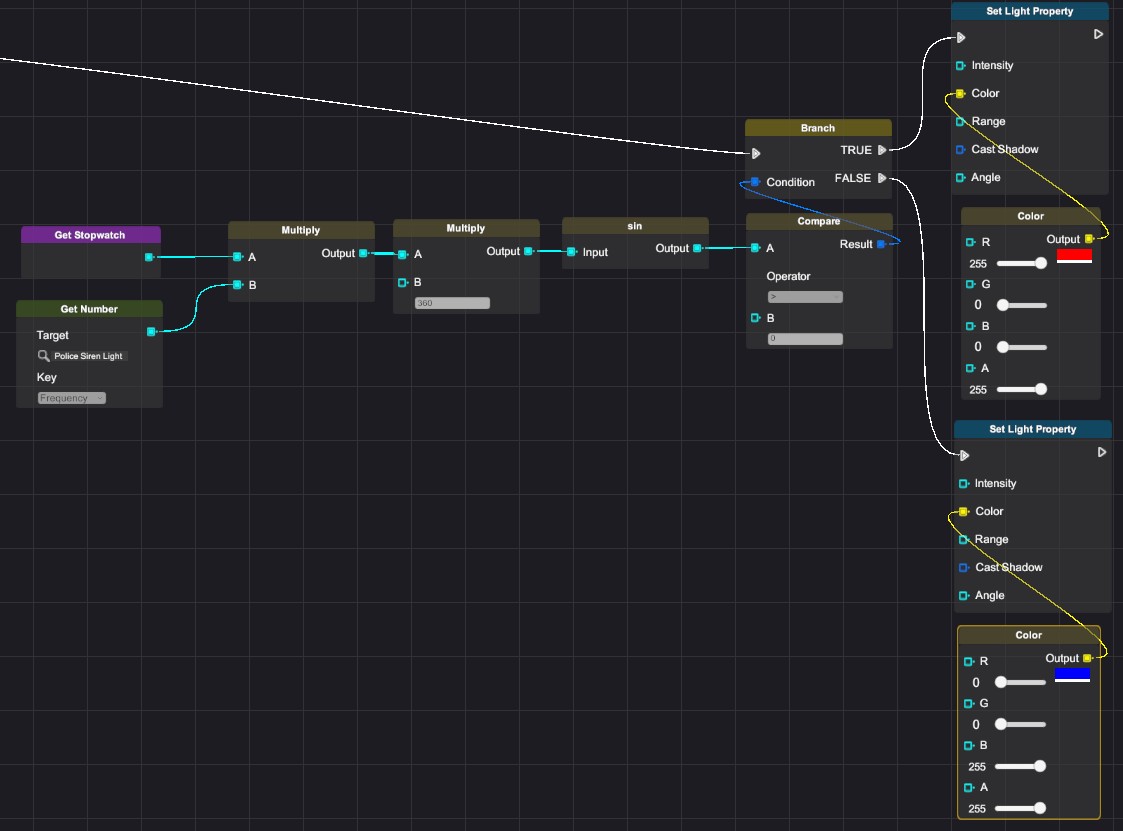
- We can also implement the red and blue colors of the siren. Add the following nodes after the previous behaviour:
Mission Complete
Congratulations! You have completed this tutorial. Take what you have learned from this tutorial and go on to create other amazing VR experiences in XRCC.